First IoT Bench Test: Arduino Wire-Up, Serial Path, and Rust Control Loop
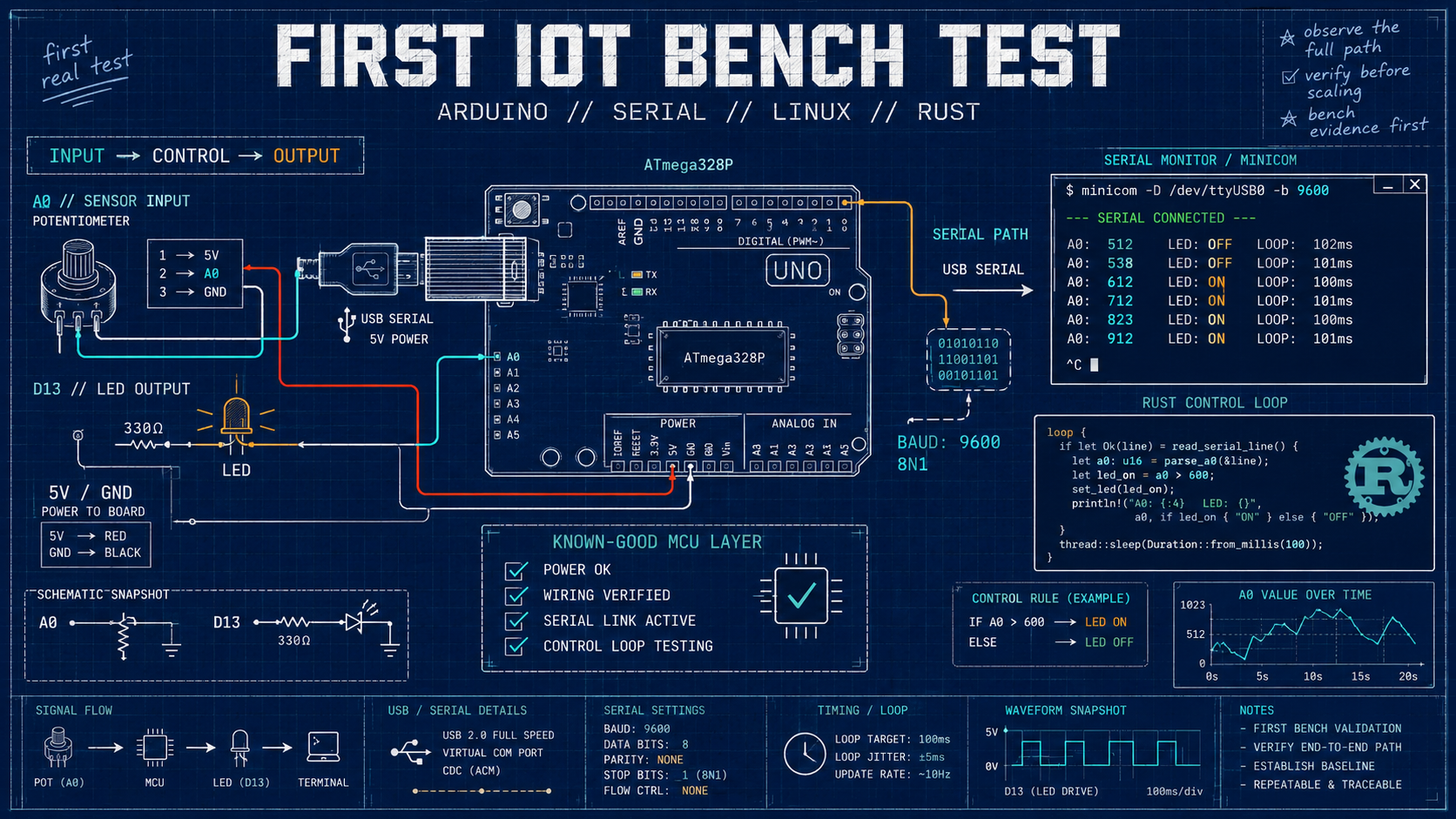
A practical Arduino bench test for the IoT rebuild: wire a simple input and output, verify serial I/O on Linux, and establish a known-good microcontroller path.
First IoT Bench Test: Arduino Wire-Up, Serial Path, and Rust Control Loop
My previous post was a high-level outline of my current skills refresh around modern IoT systems. I wanted to document the journey because I have been asked by people in the past how the pieces of an IoT system actually fit together once you get past diagrams and product names. I have written about parts of this work before through my Master’s Thesis and industry publications, but those publications leave out some of the practical bench-level details.
This post starts at the bench. The goal is to wire up an ATMEGA328-based Arduino, read a simple analog input, control an output, and confirm that Linux can talk to the board over serial. It is not a complex circuit, but that is the point: before adding radios, dashboards, databases, AI tooling, or cloud services, I want one known-good hardware and programming path I can trust.
Where this fits into the overall IoT system
Microcontrollers sit at the physical edge of an IoT system. They read the world through sensors and affect the world through actuators. In an HVAC system, for example, a controller might read temperature and humidity, send that data upstream, and respond to commands that switch a fan, damper, or relay.
That edge layer can get deep quickly. You can spend a lot of time choosing the right controller, working through power constraints, selecting sensors, building firmware, and deciding how firmware should be tested and deployed. For this post, I am keeping the toolchain intentionally simple by using the Arduino IDE. Later posts can move into alternatives once the first path is working.
The Physical Wire-Up
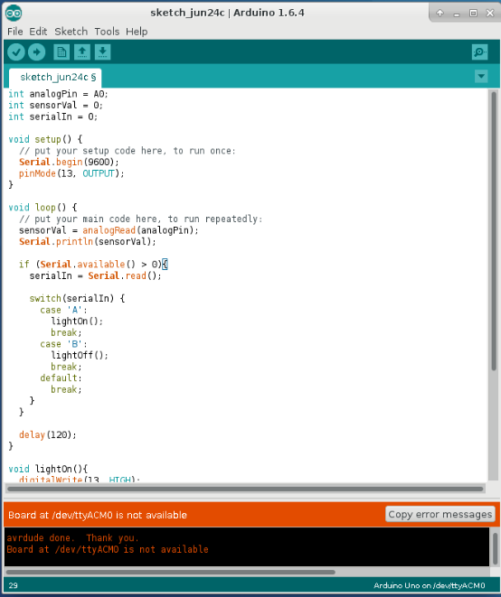
The circuit is the embedded equivalent of “Hello, World.” I have not used some of these electronics kits in a while, and after a few moves I do not want to assume every board, jumper, or component is still in good condition. A simple wire-up gives me a repeatable check before I start building larger parts of the system.
Most of the IoT projects I have worked on follow the same basic pattern: a microcontroller reads a sensor, sends that measurement to an attached computer, and receives commands back from the computer to change an output. That means the first useful test is not only blinking an LED. It is proving that data can move in both directions between the board and a Linux system.
For this test, the potentiometer stands in for a sensor and the onboard LED stands in for an actuator. Turning the knob gives us a changing analog value. Sending a command from Linux turns the LED on or off.
Programming From The IDE
Getting started with microcontrollers today is much simpler than it used to be. You do not need AI tooling to get this first pass working; the examples and language reference on Arduino’s website are enough.
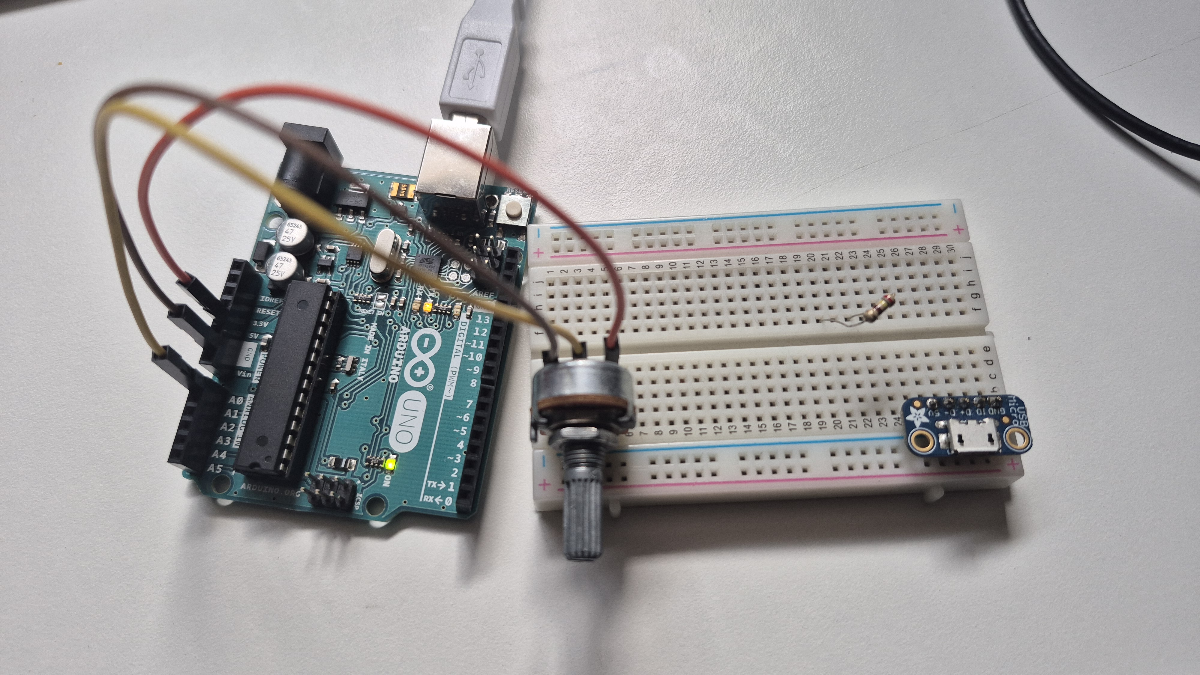
Since we are using an Arduino Uno, the bootloader is already set up for sketches uploaded from the Arduino IDE. This first sketch only needs two main pieces: setup() to configure serial communication and the LED pin, and loop() to continuously read the analog input and respond to serial commands.
int analogPin = A0; // We will attach the potentiometer to pin A0
int sensorVal = 0; // Set the default value to zero
int serialIn = 0; // Store commands received over serial

void setup(){
  // Set up the microcontroller to read from serial port at 9600 baud, defaults to 8N1
  Serial.begin(9600);

  // Pin 13 usually has the onboard LED attached on Arduino boards
  pinMode(13, OUTPUT);
}

void loop(){
  // Read the value of the potentiometer and print the value over serial
  sensorVal = analogRead(analogPin);
  Serial.println(sensorVal);

  // Process the value sent over serial. If A then turn LED on, If B then turn LED off
  if (Serial.available() > 0){
    serialIn = Serial.read();

    switch(serialIn) {
      case 'A':
        lightOn();
        break;
      case 'B':
        lightOff();
        break;
      default:
        break;
    }
  }

  delay(120);
}

void lightOn(){
  // Turn on LED
  digitalWrite(13, HIGH);
}

void lightOff(){
  // Turn off LED
  digitalWrite(13, LOW);
}
For a quick check, compile and upload the sketch from the Arduino IDE. Then use minicom to open the serial port from Linux.
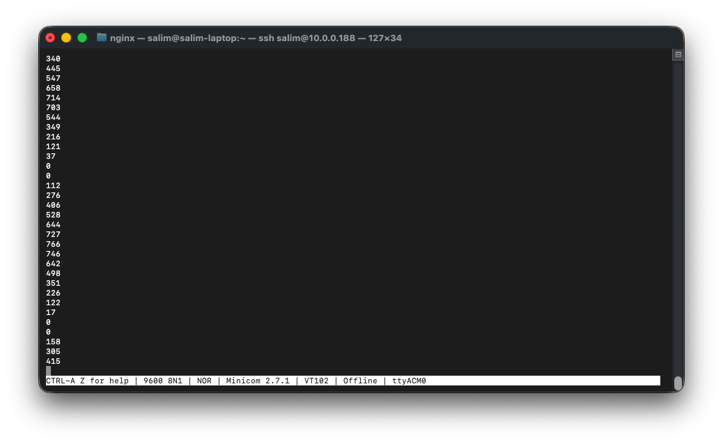
$ minicom -D /dev/ttyACM0At this point, the terminal should display values from analog pin 0. Turn the potentiometer and the numbers should change. Press A or B to turn the LED on or off. That confirms the board, sketch, USB serial connection, analog input, and digital output are all working together.
In the past, I mostly used C when I needed a Linux program to communicate with an Arduino. Since this series is partly about refreshing and updating my own toolchain, I am rebuilding that host-side program in Rust.
The old C version used pthreads: one thread handled keyboard input and another handled serial reads. Rust gives you stronger safety guarantees, but it also forces a different way of thinking about shared state, ownership, and concurrency. I will cover that in more depth later. For now, the important part is that the host program can listen to the Arduino while still accepting keyboard commands.
use std::error::Error;
use std::io::{self, Read, Write};
use std::sync::mpsc;
use std::thread;
use std::time::Duration;

enum UserCommand {
    SendA,
    SendB,
    Quit,
}

fn main() -> Result<(), Box<dyn Error>> {
    let mut port = serialport::new("/dev/ttyACM0", 9600)
        .timeout(Duration::from_millis(100))
        .open()
        .expect("Failed to open serial port");

    let (tx, rx) = mpsc::channel::<UserCommand>();

    // Keyboard thread.
    thread::spawn(move || {
        let stdin = io::stdin();

        loop {
            let _ = io::stdout().flush();

            let mut input = String::new();

            if stdin.read_line(&mut input).is_err() {
                continue;
            }

            match input.trim() {
                "q" => {
                    let _ = tx.send(UserCommand::Quit);
                    break;
                }
                "a" => {
                    let _ = tx.send(UserCommand::SendA);
                }
                "b" => {
                    let _ = tx.send(UserCommand::SendB);
                }
                _ => {
                }
            }
        }
    });

    let mut buf = [0u8; 256];

    loop {
        // Check keyboard commands without blocking serial reads.
        while let Ok(cmd) = rx.try_recv() {
            match cmd {
                UserCommand::Quit => {
                    println!("Quitting...");
                    return Ok(());
                }
                UserCommand::SendA => {
                    port.write_all(b"A\n")?;
                    port.flush()?;
                }
                UserCommand::SendB => {
                    port.write_all(b"B\n")?;
                    port.flush()?;
                }
            }
        }

        // Continuously read from serial port.
        match port.read(&mut buf) {
            Ok(n) if n > 0 => {
                print!("{}", String::from_utf8_lossy(&buf[..n]));
                io::stdout().flush()?;
            }
            Ok(_) => {
                // No bytes read.
            }
            Err(ref e) if e.kind() == io::ErrorKind::TimedOut => {
                // Normal. Timeout keeps the loop responsive to keyboard commands.
            }
            Err(e) => {
                return Err(Box::new(e));
            }
        }
    }
}
Once this code is running, the screen should list the values from analog pin 0. Press a or b to send LED commands, or q to quit.
Where are we at now in terms of the IoT stack
This is still the lowest layer of the IoT stack, but it gives us something useful: a controlled edge device. The board can produce a changing sensor-like value, the Linux machine can read that value, and the Linux machine can send a command back to change an output.
That matters because every later layer needs a trustworthy source of data. If a dashboard shows the wrong value, a database misses records, or a cloud service receives malformed messages, this bench setup gives us a known place to start debugging. We can turn the potentiometer, watch the serial output, send a command, and isolate whether the problem is at the device, host, network, or application layer.
The newer part for me was the Rust host program. The hardware test is standard, but rewriting my C serial workflow in Rust exposed the first real modernization topic in this series: concurrency, ownership, and how to structure a small tool that reads from hardware while accepting user input.
Next Step
The next step is to replace the simulated input and output with real components.
The potentiometer and onboard LED were useful because they kept the first test controlled. Now that the board, sketch, serial connection, and Linux-side program are working, we can start introducing actual sensors and actuators: temperature, humidity, light, motion, relays, motors, or whatever fits the next build.
That is where the IoT stack starts to feel less abstract. Instead of only proving that numbers move across serial, the next test should capture a real condition from the environment and drive a physical response from the board.